2023-01-03 16:59:10
In recent years, my country's heavy machinery metal structure manufacturing industry has made remarkable achievements. Traditional industries with high energy consumption, high consumables, low efficiency, poor working environment and low degree of automation should be thoroughly improved, and the industry should be promoted to develop in the direction of high quality, high efficiency, energy saving, low cost, environmental friendliness and automation. Transform it into a competitive advantage in science and technology, and promote enterprise progress and industrial upgrading. Only by using advanced management methods and CAD/CAM integrated manufacturing technology can enterprises remain invincible in the fierce market competition.
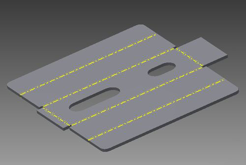
1 Pro/E integrated manufacturing technology
Pro/E software adopts object-oriented unified database and parametric modeling technology , has the functions of conceptual design, basic design and detailed design, and provides an excellent platform for the integrated manufacturing of molds.
The traditional unfolding method and the modern PRO/E unfolding method of the bent metal structure are compared and analyzed, and the application examples are listed. The matters needing attention in the bending process of PRO/E unfolding method are summarized. The superiority and practicability of the unfolding method of PRO/E applied in the unfolding of bending parts are clarified. A practical tool is provided for unfolding modern bent metal structures.
In the modern metal structure manufacturing industry, with the wide application of CNC processing equipment such as CNC cutting machines and CNC bending machines, the processing technology of metal structures has also made a qualitative leap. The extensive expansion of traditional bending parts processing technology will be replaced by new software applications.
The application of this new process brings advantages such as process simplification, high efficiency, and good processing quality, but requires high precision of the unfolded drawing. Therefore, the drawing of accurate unfolding diagram in processing has become the first problem to be solved.
2 Pro/E sheet metal module deployment
At present, the popular 3D CAD software such as SolidWorks, Radan, PRO/E/ENGINEER all have sheet metal design modules, which can conveniently complete sheet metal design and obtain the required blanking expansion diagram. Improve design quality and efficiency. The following is a brief introduction to the design process through a typical case.
Example: 45° oblique tee
Tee pipe (see Figure 1).
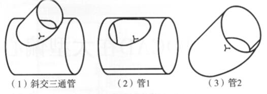
Figure 1 Structural diagram of 45° oblique tee pipe
Among them, the blanking calculation steps of tube 1 are as follows:
(1) Create a new sheet metal part and set the template as "mmns_part_sheetmetal ";
(2) Select the drop-down menu "Insert/Thin Plate Protrusion/Rotate" command, draw a sketch on the top reference plane, set the rotation axis as Front, rotate symmetrically on both sides, reserve a machining allowance of 1°, and determine the rotation angle 359°, set the corresponding material thickness (see Figure 2);
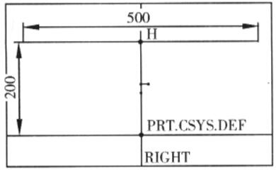
Figure 2 Setting sketch
(3) Select the "Insert/Cut/Rotate" command, set the sketch reference plane as Front (see Figure 3), draw a sketch, and set the 45° reference axis as the rotation axis, both sides Symmetrical 360° rotating material removal;

Figure 3 Sketch
(4) Select the "Insert/Bend Operation/Expand" command, select the sheet metal unfolded fixed surface to reserve a seam at 359°, and after unfolding all the surfaces regularly, you can get the tube 1 The blanking expansion diagram (see Figure 4);

Figure 4 Pipe 1 downward slanted expansion
In this example, the user can achieve the same effect by using the extrude cutting or drilling command.
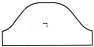
Figure 5: Tube 2 downward slope expansion
</


+86 13713208199